The XLR connector was invented by James H. Cannon, founder of Cannon Electric in Los Angeles, California (now part of ITT Corporation), and for this reason it was sometimes colloquially known as a Cannon plug or Cannon connector. Originally manufactured as the Cannon X series, by 1950 a latching mechanism was added (Cannon XL) and by 1955 a version surrounding the female contacts with a synthetic rubber polychloroprene (neoprene) insulation using the part number prefix XLR. There was also an XLP series which used a hard plastic insulation, but was otherwise the same. ITT Cannon originally manufactured XLR connectors in two locations: Kanagawa, Japan and Melbourne, Australia. The Australian operation was sold to Alcatel Components in 1992 and then acquired by Amphenol in 1998. ITT Cannon continues to manufacture XLR connectors in Japan.* ( Wikipedia)
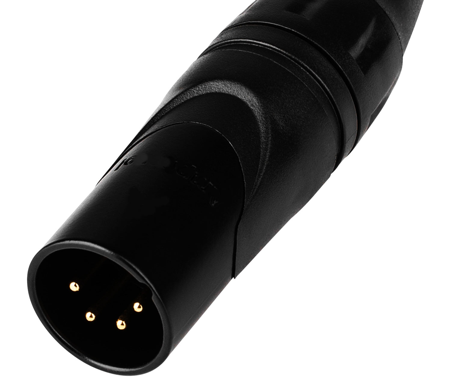
The XLR connectors are circular in design and have between three and seven pins. They are most commonly associated with balanced audio interconnection . XLR connectors are available from a number of manufacturers and are covered by an international standard for dimensions, IEC 61076-2-103

At present, we make use of XLR cables in different types of audio applications which range from professional recording sessions to even live performances. These cables consist of a circular connector as well as three pins which help in producing balanced microphone plus line-level signals over a long distance. The ability of an XLR cable to produce a balanced signal implies that reduced unwanted noise is going to be received by the eventual audio signal from any external electrical interference. In this way, the original audio signal is going to be preserved even in the close vicinity of other electronic gadgets over a long distance.
These days, the XLR connectors can be obtained in both female as well as male versions. The female connectors have been designed to connect pin 1 initially prior to contact is made by the other pins once the male connector has been inserted. With the ground connection established before the signal lines are connected, the insertion (and removal) of XLR connectors in live equipment is possible without picking up external signals (as usually happens with, for example,RCA connectors).
The number of pins is going to differ, as of 2016, XLR connectors are available with up to 10 pins, and mini XLR connectors with up to eight.
The terminology for labeling the corresponding members of a pair of mating connectors follows the usual rules for the gender of connectors: a 'male' connector is the one with pins on the smallest element, 'female' has corresponding receptacles. For most XLR, plugs are male and sockets are female. A common misnomer is that 'plugs' are free connectors and 'sockets' are panel-mounted. There is a loose convention for audio work that signals are generated by equipment with male pins and transmitted to that with female receptacles.
The unbalanced audio cables consist of a couple of wires, wrapped with insulation, which function is to be conductor for carrying both the ground as well as the signal. These can be vulnerable to any noise produced by the interference from electrical fields of any nearby electronic gadget.
Balanced cables on the other side come with three wires which function as conductors, namely, negative, positive, as well as ground. The audio signal is carried by both the positive as well as negative wires having opposite polarities. This implies that any noise resulting from any external interference source is going to be nullified.
The XLR cables is balanced cables which have circular connectors along with as many as three pins – positive, negative, as well as ground. The ground signal with XLR cable is always the “Pin 1”. A positive audio signal along with a ground signal plus a negative audio signal will be delivered by the XLR cable once two balanced devices are connected. In addition to being reversed, both positive and negative audio signals are similar to each other. In the event of any electrical interference, this noise enters both the negative and positive audio signals. Once both signals reach the balanced device at the end, one audio signal will be reversed. These two signals are similar in every possible way. However, the noise that was on the audio signal is now reversed. In fact, they will cancel each other out when the original noise is combined with the reverse. In this case, only the original audio signal will remain.

Leave a comment
This site is protected by hCaptcha and the hCaptcha Privacy Policy and Terms of Service apply.